Montage Docking Station
Assembly drawing
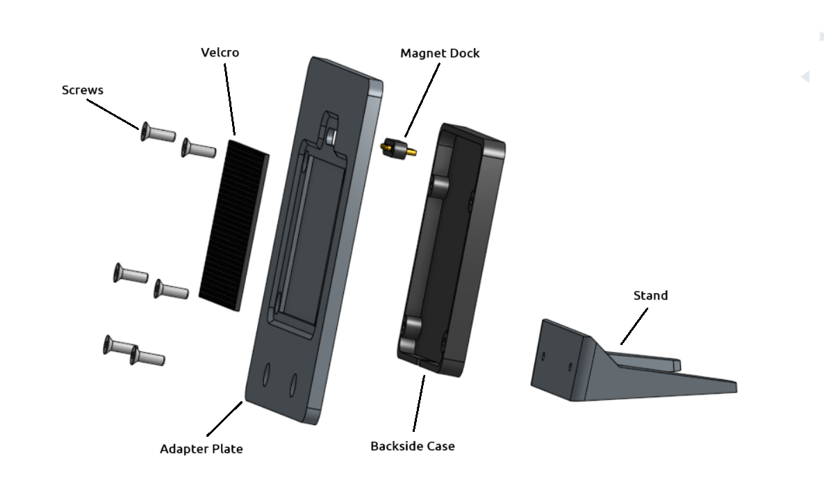
Abb.: Montage Docking Station
Bill of materials
Pos. |
Number |
Designation |
Material |
Source |
|---|---|---|---|---|
1 |
1 |
Adapter Plate |
ABS / ASA |
|
2 |
1 |
Backside Case |
ABS / ASA |
|
3 |
1 |
Stand |
ABS / ASA |
|
5 |
1 |
Magnet Dock |
4 Pol. |
|
7 |
1 |
Velcro D 3 mm |
50 X 40 mm |
|
8 |
6 |
M3x6 |
Steel/Nickel |
Assembly instructions
The docking station is assembled according to the assembly instructions in the following order:
- Print housing parts
The housing parts can be printed with a standard 3D printer. Use the following settings:
0.4 Mm nozzle
Wall thickness 1 mm
Wall thickness of the top and bottom: 1 mm
Fill level 30%
Support enabled
- Glue the magnetic dock to the back panel using hot glue.
Ensure the magnetic dock is centered and thoroughly coated with hot glue. Make sure no hot glue seeps out. Remove any excess hot glue if necessary.
Soldering point
Aderfarbe
Component
Pin 1
Rot, 5 V
Magnet Dock
Pin 2
White, D-
Magnet Dock
Pin 3
Yellow, D+
Magnet Dock
Pin 4
Black
Magnet Dock
Warning
When attaching the magnetic dock, ensure it is oriented correctly. It must align with its counterpart in the OBP40. If you intend to use multiple OBP40s with docking stations, all contacts must be installed in the same orientation so that all different devices can be charged in the docking station.
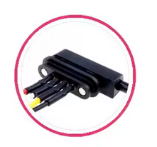
Fig.: Alignment of the two magnetic dock parts
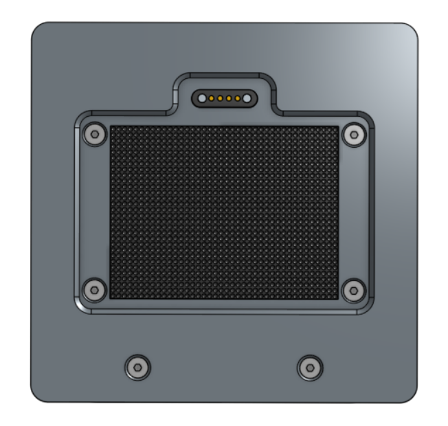
Fig.: Magnetic dock in mounting plate
- Cut the hook and loop tape to 50 x 40 mm and glue it into the recess of the back panel.
Stick the Velcro strip in place so that it does not protrude at the edges and is completely inside the recess.
- Connect plastic parts with M3 screws
Hint
If you need to re-tighten the screws, first turn them counterclockwise until you feel the threads click into place, and only then tighten them clockwise. This will prevent damage to the threads.