How it works
Use
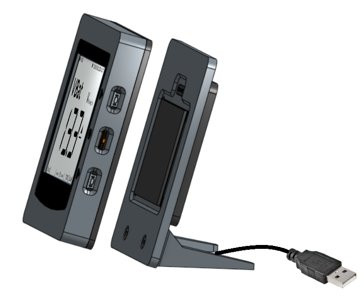
The OBP40 can be used as a standalone mobile device or as a stationary device in a docking station. To use it as a mobile device, an optional LiPo battery must be installed. The battery can be charged locally via the USB port on the left side and via the docking station. A magnetic dock on the back of the OBP40 allows for charging in the docking station. As a mobile device, the OBP40 can operate independently for up to 8.5 hours. If the battery voltage drops below a critical minimum, the OBP40 automatically enters deep sleep mode to conserve power and protect the battery.
Fastening
The OBP40 can be attached in various ways, taking into account both metal and plastic boats.
Attachment via magnets to metal surfaces and in the docking station
Attaches to any surface and in the docking station via Velcro strap
Attachment via magnets to mounting plate
Attachment via Velcro strap to the mounting plate
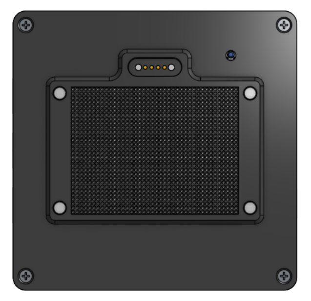
Fig.: Back of OBP40 with magnetic dock and Velcro strap
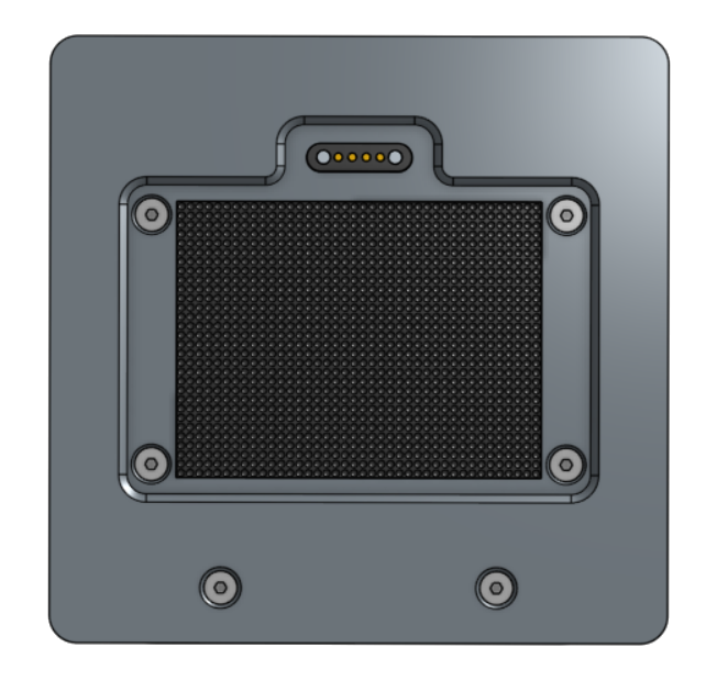
Fig.: Docking station support surface
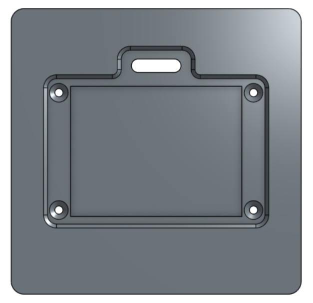
Fig.: Mounting plate
There are two basic mounting options: magnets or hook-and-loop fasteners. Depending on the situation, you can choose one or both. The 50 x 40 mm hook-and-loop fastener provides sufficient adhesion and can be used on any surface. For those who prefer a fixed position for the OBP40, the mounting plate can be used. This allows for precise alignment of the display with other devices. The OBP40 self-centers via the conical recess in the mounting plate. The mounting plate can optionally be equipped with a magnetic dock for powering the OBP40.
Warning
Strong neodymium magnets are used as mounting magnets, which can distort the Earth’s magnetic field at the compass. Maintain a minimum distance of 2 meters from compasses and check the deviation table for additional discrepancies. This also applies to electronic compasses.
Note
A 5V supply voltage is applied to the two outer spring contacts of the magnetic dock. The two inner spring contacts transmit the USB data. Avoid short circuits with metallic objects at the contacts and protect the contacts from moisture.
WiFi connection
Data transmission in both mobile and stationary operation occurs exclusively via a 2.4 GHz Wi-Fi connection. The OBP40 receives its data from other devices via NMEA0183 as a TCP data stream. Data sources can include an OBP60, an M5Stack, SignalK, AvNav, or other sources.
Gateway

The OBP40 has an integrated gateway that can exchange data bidirectionally between NMEA0183 and NMEA2000. This involves translating the data from one bus into the data from the other bus. The translation works in both directions.
Note
It should be noted that not all NMEA2000 data can be translated into NMEA0183 data, because suitable telegrams in NMEA0183 do not always exist.
Configuration
The OBP40 has an integrated access point and a small web server for device configuration. Unlike other commercial devices, the OBP40 is configured exclusively via the web. A mobile phone, for example, can be used for this purpose. This makes device configuration significantly easier and more convenient. Up to 10 display pages can be freely defined on the device. The user can choose between numeric and graphical display pages. Any data from the bus systems can be displayed on each numeric display page. The data content on the graphical display pages is predefined, as they offer specific functionalities.
Display and operation
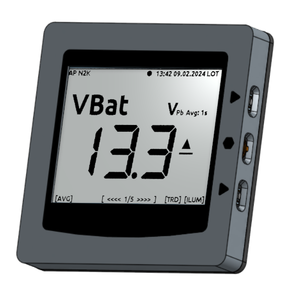
The display uses an e-paper screen. It offers high contrast and good readability even in bright sunlight. Furthermore, it consumes very little energy.
The display pages are selected using a jog dial with a pressure point and two additional buttons on the right side. Depending on the display page, some settings can also be adjusted using the buttons. These settings then apply exclusively to that display page and are saved, so they are retained when switching pages.
USB-Ports
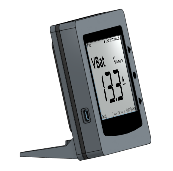
The OBP40 has a USB port on the left side, which is simultaneously transmitted to the docking station via contacts on the back. The docking station has its own USB cable, which can be used to connect to other devices. As long as the OBP40 is in the docking station, the USB connection is established via the docking station’s USB cable.
Hint
Only one USB connection to the OBP40 is permitted. Use either the left USB port on the OBP40 or the USB cable of the docking station. Both USB connections must not be used simultaneously.
Expansion port

Fig.: Circuit board pinout (Elecrow)
The board features a 20-pin GPIO expansion port on the top side. This allows for the optional connection of additional hardware such as:
CAN-Bus (NMEA0183)
RS485-Bus (NMEA0183)
I2C bus
1Wire-Bus
Buzzer
GPS receiver (RS232)
Analog input for voltage measurement
To enable data exchange via NMEA2000 or NMEA0183, optional add-on modules are required, which must be connected to the expansion port. The I2C and 1-Wire buses, however, can be used directly. Details on the GPIO expansion port pinout can be found in the chapter GPIO expansion port.
Warning
Connecting additional hardware requires knowledge of electronics to ensure correct connection. Signal levels at the connectors must not exceed 3.3 V, and it is essential to check whether the connectors are being used as inputs or outputs. The exposed connectors are unprotected. Incorrect use of these connectors can cause irreparable damage to the processor.