Montage OBP40
Assembly drawing
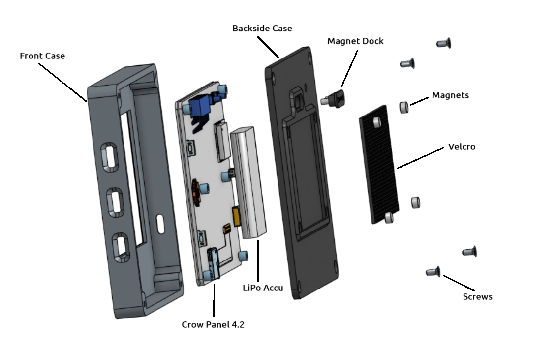
Abb.: Montage OBP40 Main Unit
Bill of materials
Pos. |
Number |
Designation |
Material |
Source |
|---|---|---|---|---|
1 |
1 |
Front Case |
ABS / ASA |
|
2 |
1 |
Backside Case |
ABS / ASA |
|
3 |
1 |
Crow Panel 4.2 |
FR4 |
|
4 |
1 |
LiPo-Battery 1 |
3.7V, 1200mA |
|
5 |
1 |
Magnet Dock |
4 Pol. |
|
6 |
4 |
Magnets D5x3 |
Neodym |
|
7 |
1 |
Velcro D 3 mm |
50 X 40 mm |
|
8 |
4 |
M2.5x4 |
Steel/Nickel |
- 1
LiPo battery: 52 x 43 x 6 mm
Assembly instructions
The housing is assembled according to the assembly instructions in the following order:
- Print housing parts
The housing parts can be printed with a standard 3D printer. Use the following settings:
0.4 Mm nozzle
Wall thickness 1 mm
Wall thickness of the top and bottom: 1 mm
Fill level 30%
Support enabled
Hint
The front panel is designed for two-color printing. The black areas are implemented as 0.2 mm thick inlays. Consult your printer’s documentation for two-color printing instructions. If your printer does not support two-color printing, you can also print the front panel in a single color. Simply use the STL file for this.
- Unscrew the back and spacers of the Crow Panel 4.2
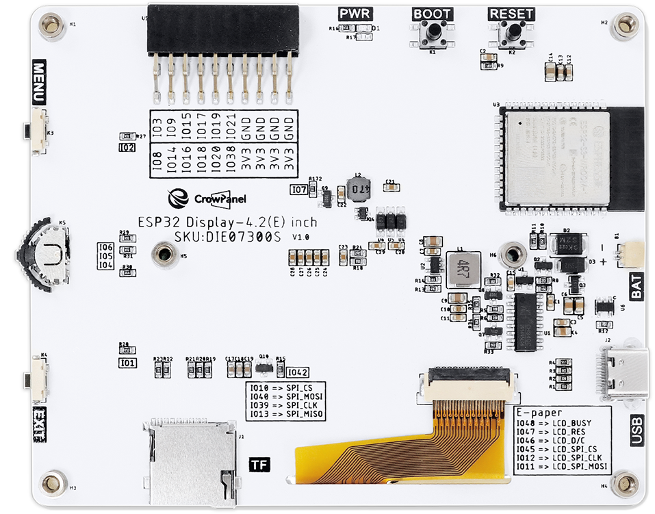
Fig.: Crow Panel 4.2 Mainboard Top (Elecrow)
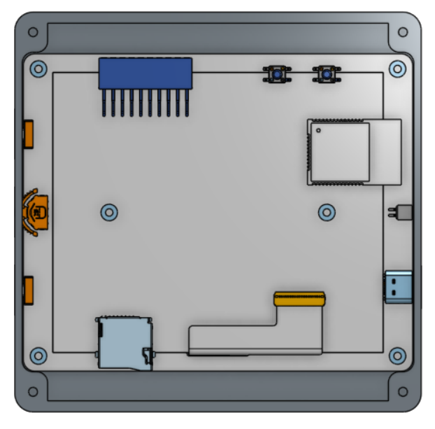
- Insert the Crow Panel 4.2 circuit board into the front cover.
Insert the circuit board into the front panel, starting from the side with the buttons.
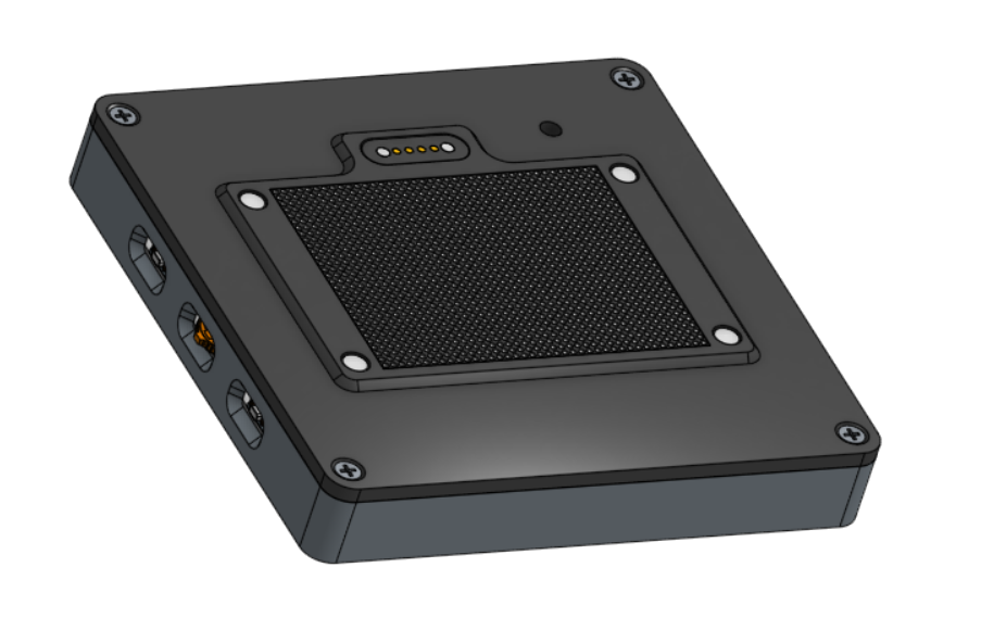
- Glue the magnetic dock to the back panel using hot glue.
Ensure the magnetic dock is centered and thoroughly coated with hot glue. Make sure no hot glue seeps out. Remove any excess hot glue if necessary.
- Glue magnets into the back panel using hot glue.
Before inserting the magnets, put a small dab of hot glue into the recess and quickly insert the magnet so that the glue doesn’t set prematurely. Make sure not to use too much hot glue in the recess.
- Cut the hook and loop tape to 50 x 40 mm and glue it into the recess of the back panel.
Stick the Velcro strip in place so that it does not protrude at the edges and is completely inside the recess.
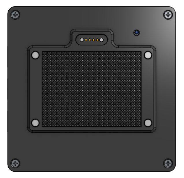
- Install the LiPo battery, magnetic dock and voltage divider, and solder the cables.
Hint
Soldering the cables requires good soldering skills and high-quality soldering tools, as the connections are very small. Use a temperature-controlled soldering iron with a fine tip and 0.5 mm diameter solder. Flux and copper tape for absorbing excess solder will simplify the process. If you are unsure about doing this yourself, contact a professional for assistance.
Warning
Take care not to cause short circuits on the circuit board with other components. Do not solder for too long at the affected points, as you may desolder components or damage traces. Check all solder joints before putting the circuit board back into operation. Use a digital voltmeter to check for short circuits at the solder joints. Keep in mind that soldering work will void the manufacturer’s warranty.
Solder the cables according to the table and the pictures.
Soldering point
Aderfarbe
Component
C5 top
Red, 3.7V
LiPo Battery
C5 below
Black
LiPo Battery
C4 links
Rot, 5 V
Magnet Dock
R2 links
White, D-
Magnet Dock
U1 Pin 5
Yellow, D+
Magnet Dock
C4 right
Black
Magnet Dock
C5 top
Rot
V-splitter
IO3
Green
V-splitter
USB-C, GND
Black
V-splitter
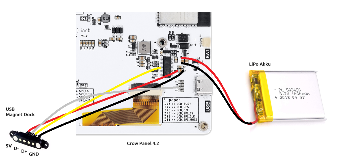
Fig.: Solder points for connecting cables
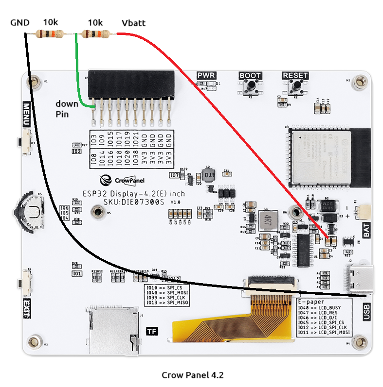
Fig.: Voltage divider for state of charge measurement
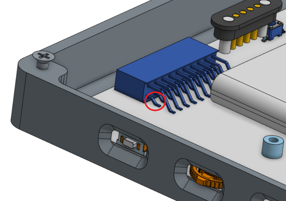
Fig.: Solder point for IO3
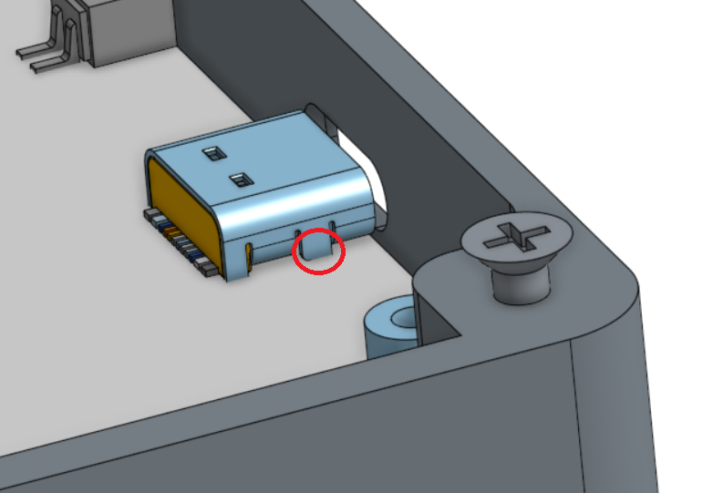
Fig.: Solder points for USB-C GND
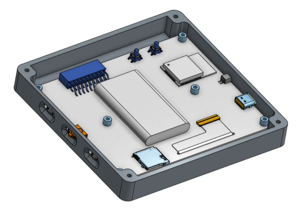
Fig.: Position of the LiPo battery on the circuit board
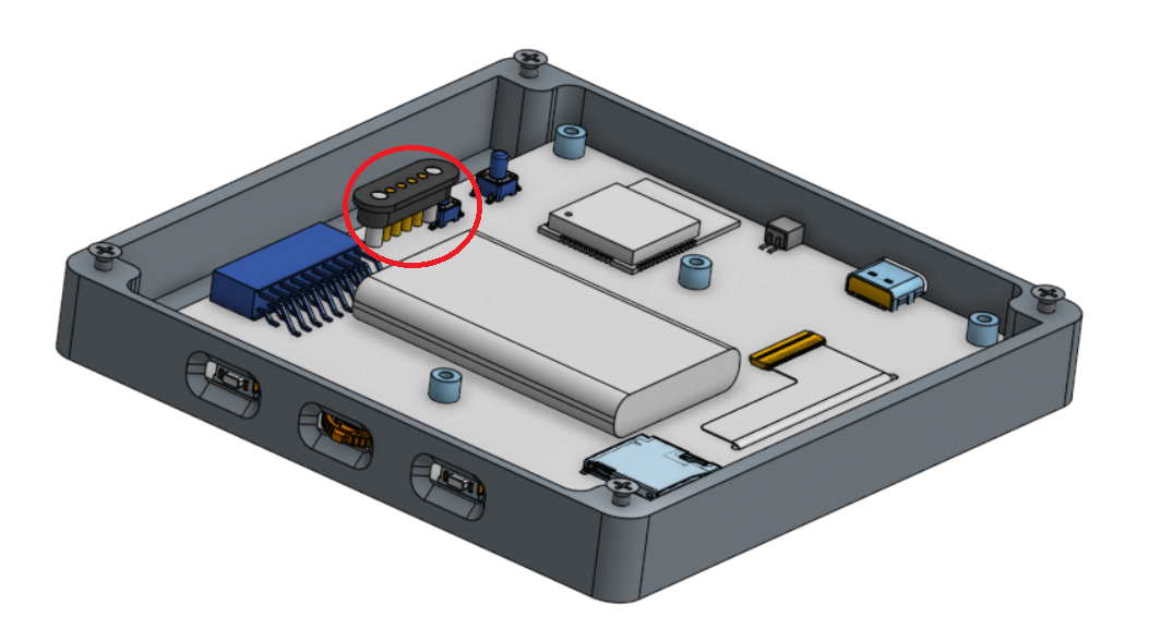
Note
Make sure to insulate the connecting cables on the magnetic dock with 3 mm heat shrink tubing. This will prevent short circuits with the circuit board.
- Place the back panel onto the front panel and connect it with M2.5 screws.
Use the screws you removed from the back of the Crow Panel 4.2. The holes in the plastic are sized so that you can screw the screws in with a little pressure. The thread will then cut into the plastic on its own.
Hint
If you need to re-tighten the screws, first turn them counterclockwise until you feel the threads click into place, and only then tighten them clockwise. This will prevent damage to the threads.
- Flashing firmware
The last step involves flashing the firmware. Follow the instructions in chapter Web-Flashtool.
Modify firmware
Note
For the firmware to display the LiPo battery and its charge level, the corresponding compiler flags
LIPO_ACCU_1200andVOLTAGE_SENSORmust be set in the firmware file platformio.ini. You will need to create a customized firmware file and activate it in the OBP60 as Update. Details on firmware creation can be found in the chapter Gitpod.