Bus systems
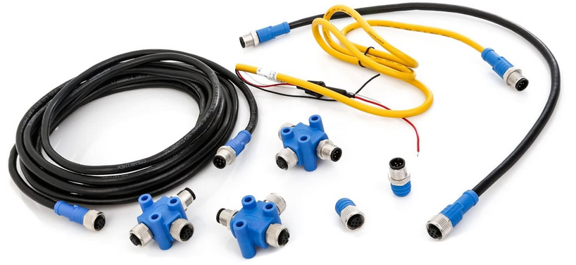
The OBP40 supports multiple bus systems via its GPIO expansion port. This chapter deals exclusively with networking the components. The necessary software configuration can be found in the following chapter Data exchange.
NMEA2000 via CAN bus (requires line drivers)
NMEA0183 via RS485/RS422 bus (requires line driver)
I2C Bus
1-Wire-Bus
USB-C

Fig.: GPIO expansion port
Above |
Function |
Below |
Function |
|---|---|---|---|
GPOI8 |
0183 You |
GPIO3 |
Analog In |
GPOI14 |
0183 RX |
GPIO9 |
0183 TX |
GPOI16 |
CAN RX |
GPIO15 |
CAN TX |
GPOI18 |
Buzzer |
GPIO17 |
1Wire |
GPOI20 |
GPS TX |
GPIO19 |
GPS RX |
GPOI38 |
I2C SCL |
GPIO21 |
I2C SDA |
3V3 |
3.3V |
GND |
Lot |
3V3 |
3.3V |
GND |
Lot |
3V3 |
3.3V |
GND |
Lot |
3V3 |
3.3V |
GND |
Lot |
Table: Occupancy of additional ports
NMEA2000 and NMEA0183 are bus systems used in the marine sector. The I2C bus and the 1-Wire bus originate from the electronics sector. Many inexpensive sensor modules can be integrated via these systems. The respective bus systems are described in more detail below.
NMEA2000
NMEA2000 is a bus system used for data transmission between electronic devices in the maritime industry. NMEA2000 uses CAN for data transmission. Transmission occurs via a central cable to which all devices are connected in parallel. Each device in the NMEA2000 network has a unique device ID to identify and address data sources and data display devices. Data is organized into Parameter Group Numbers (PGNs). PGNs are unique data IDs used to describe specific types of data, such as speed, course, temperature, etc. All devices can send and receive PGNs, and it is also possible to specify which PGNs a particular device should send or receive.
NMEA2000 specification in OBP40
Differential, bidirectional binary-based data protocol
Half-duplex with collision detection and avoidance
Bus structure (isolated)
Bus terminating on both sides
- Supported protocols
CAN (requires line driver)
Fixed data rate of 250,000 bits/s
Bus length up to 30 m (spur lines <1.5 m)
Differential data transmission
Data transmission on the CAN bus is differential. Two signals with opposite polarities are transmitted from the transmitter, which are then combined into a single signal at the receiver by subtracting them. Interference affecting both signal lines equally is eliminated by this subtraction process at the receiver. This ensures robust and interference-resistant signal transmission.
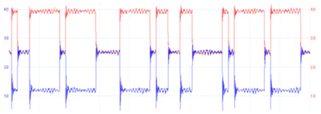
Fig.: Differential data transmission (red CAN-H, blue CAN-L)
The data rate of NMEA2000 is 250 kbps. This was chosen to ensure a sufficiently high transmission speed for a wide range of applications on boats, while simultaneously guaranteeing the most efficient use of the network. A data rate of 250 kbps allows sensor data to be transmitted in real time, which is important for a variety of applications, such as monitoring the vessel’s position, navigation and communication devices, engine systems, and other onboard systems.
Note
SeaTalk NG, SIMnet, Raynet, C-Net 2000, and CANet share some similarities with NMEA 2000. However, they differ in their specific hardware and data telegram implementations. SeaTalk NG and SIMnet are partially compatible with NMEA 2000. This means that some devices designed for SeaTalk NG and SIMnet can also communicate with NMEA 2000 devices, albeit with limitations.
Termination of the bus system
A CAN bus uses 120-ohm termination resistors at both ends of the bus system between the CAN-H and CAN-L lines. These two termination resistors correspond to the line resistance of 120 ohms and prevent signal reflections at the line ends during high data transmission rates. The CAN bus consists of a long bus segment (backbone) with short branch lines less than 1.5 m in length. A star topology of the bus system is not permitted. The two termination resistors must only be installed at the bus end.
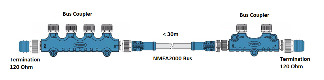
Fig.: CAN bus termination for NMEA2000 via T183
Warning
Some devices have built-in termination resistors that can be switched on or off using appropriate switches. Before adding new devices to your NMEA 2000 network, verify whether integrated termination resistors are used and how they are configured. Incorrectly terminated buses can cause transmission problems that are difficult to diagnose.
Tip
To determine if only two resistors are active on the NMEA bus, you can use a digital voltmeter. When measuring the resistance between the CAN-High and CAN-Low lines on a de-energized NMEA bus, you should measure approximately 60 ohms. If the resistance is significantly less than 60 ohms, there are other devices on the bus system whose termination resistors are incorrectly active. While continuously measuring the resistance, disconnect one device at a time from the NMEA2000 bus until the resistance value increases significantly. The termination resistor of the last device disconnected should be deactivated. If the resistance value is still not 60 ohms, look for other devices with obviously activated termination resistors.
NMEA2000 Cable
Only high-quality, waterproof, and shielded industrial cables should be used as bus cables. Marine retailers offer a wide selection of products with M12 connectors that are very suitable for this purpose.
Tip
In industrial settings, you can find equivalent cables with M12 connectors that are significantly cheaper and can also be used. Make sure to look for connectors with A-coding. The index notch is located between pins 1 and 2.
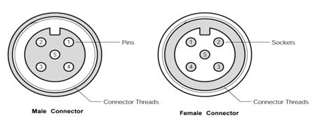
Fig.: Plug and socket (view of contacts)
The pinout and wire colors are shown in the table below. Note that the color coding may differ for industrial cables. In that case, you will need to determine the wire colors for each pin using an ohmmeter.
Pin |
Occupancy |
Color |
Meaning |
|---|---|---|---|
1 |
Shielding |
Without |
Umbrella weave |
2 |
+12V |
Rot |
Supply voltage |
3 |
GND |
Black |
Table-Mass |
4 |
CAN-H |
White |
CAN High-Signal |
5 |
CAN-L |
Blue |
CAN Low-Signal |
Table: NMEA2000 connector pinout
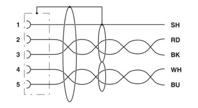
Fig. NMEA2000 bus cable with shielding
Anyone wishing to manufacture their own bus cables should use cables comparable to the type “Lapp Busleitung UNITRONIC 2 x 2 x 0.34 mm²”.
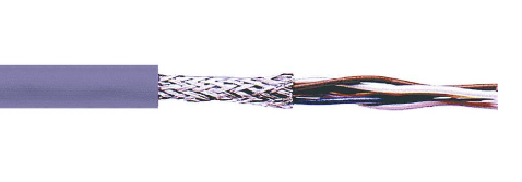
Abb. CAN-Buskabel
This cable consists of two pairs of single wires twisted together and additionally surrounded by an outer braided shield. One twisted pair is used for CAN-H and CAN-L, and the other pair for GND and 12V. The braided shield is connected to GND at only one end of the cable. This ensures optimal results and a safe and durable installation. Cables thinner than 0.34 mm² should not be used if power is to be supplied from the bus. The total length of the bus cable should not exceed 30 m.
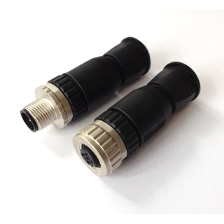
Fig.: NMEA2000 connector for self-assembly
Note
SeaTalk NG and Simnet use proprietary connectors that are not compatible with NMEA2000. However, data exchange between these networks is possible using appropriate converter cables. Generally, mixing different bus technologies should be avoided.
Wiring for NMEA2000
NMEA2000 uses a bus structure. The main bus contains one or more bus coupler units, through which the respective devices are connected. The bus length must not exceed 30 m, and the branch lines to the devices should not be longer than 1.5 m. Termination resistors are located at the ends of the main bus for bus termination. The power supply for the NMEA2000 bus is shown in the lower image via the plotter.

Fig.: NMEA2000 bus system with sensors and display devices
To connect the OBP40 to the NMEA2000 bus, a CAN bus driver is required. The CAN-H and CAN-L connections are connected to the CAN bus. The ground wire does not need to be connected.
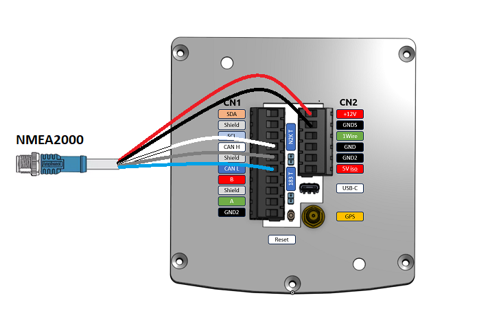
Fig.: NMEA2000 connection
Compatibility with Simnet and SeaTalk NG
Simnet and SeaTalk GN have limited compatibility with NMEA2000. Both bus systems use their own connector systems and some proprietary NMEA2000 telegrams. Most common NMEA2000 bus telegrams are supported by both systems. Simnet and SeaTalk GN bus systems can be connected to an NMEA2000 bus system using special, simple passive adapter cables. The OBP40 can then process information from Simnet or SeaTalk GN via Wi-Fi using the SeaSmart protocol and also send information to these bus systems. Proprietary telegrams are not supported, but are transmitted and forwarded within the bus system.
NMEA0183
NMEA0183 is a standard for serial data transmission in the maritime industry. It defines a format for transmitting information between navigation devices and other electronic equipment on boats. NMEA0183 is a widely used standard, supported especially by many older devices.
Specification NMEA0183 in OBP40
Serial, unidirectional data protocol based on ASCII
Point-to-point connection (isolated)
Simplex without collision detection and avoidance
Bus termination at the receiver
- Supported protocols
RS422 (Standard)
RS485
Data rate 1,200…460,800 Bd variable
Power supply for sensors and display devices via 12V vehicle electrical system
Bus length up to 1000 m (depending on data rate and cable type)
Cable type not specified
Connector type not specified
Data transfer
Data transmission in the OBP40 is half-duplex and serial, using two simple cables. This means that you can either send or receive; both simultaneously are not possible. The standard data rate is 4800 baud, which is quite slow by today’s standards, but allows bus lengths of up to 1000 m. The following settings can be used for data transmission rates:
1.200 Bd
2.400 Bd
4.800 Bd
9.600 Bd
14.400 Bd
19.200 Bd
28.800 Bd
38.400 Bd
56.600 Bd
57.600 Bd
115.200 Bd
230.400 Bd
460.800 Bd
Depending on the data rate and protocol, the permissible cable lengths can vary. These values should be observed in actual operation.
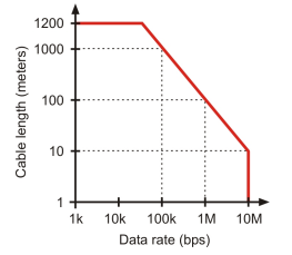
Fig.: Permissible cable lengths for RS422 and RS485
Transmission rate [Bd] |
Permissible cable length [m] |
|---|---|
4.800 |
300 |
9.600 |
152 |
19.200 |
15 |
57.600 |
5 |
115.200 |
2 |
Table: Permissible cable lengths for RS232
Data transmission uses differential signals, similar to NMEA2000. This allows common-mode interference to be reliably suppressed over long cable lengths.

Fig.: RS422 transmission model transmitter - receiver
Multiplexer
Overall, NMEA0183 is a useful standard for transmitting navigation data on boats, but it has its limitations and cannot compete with more modern technologies like NMEA2000 in all use cases. For example, to combine data from multiple sources, such as sensors, into a single data stream, multiplexers are necessary in the NMEA0183 world.
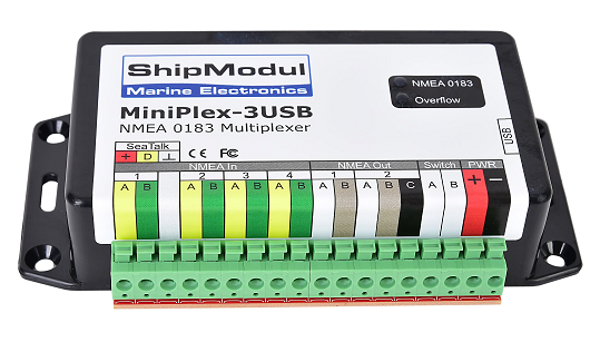
Abb.: NMEA0183 Multiplexer (Ship Modul)
The multiplexer receives various data telegrams on different ports and outputs the combined data stream from multiple sensors on a new data port. This allows multiple sensor signals to be transmitted over a single line to a data terminal such as a plotter or a multifunction display. Many multiplexers also offer the option of suppressing specific data telegrams within the data stream using a filter function. This allows, for example, only the necessary data to be transmitted to an autopilot or prevents ambiguities caused by multiple GPS receivers.
NMEA0183 Telegram Structure
NMEA0183 telegrams are quite simple in structure and are transmitted as ASCII data records. An NMEA0183 telegram consists of the following information.
Identifier
Telegram type
Sensor data
Unit
Status
CRC-Checksumme
Depending on the complexity of a telegram, multiple sensor data points or status information can be transmitted in a single telegram. The following is an example of a telegram from a depth gauge.
DBT - Depth below transducer
$–DBT,a.a,b,c.c,d,e.e,f*hh<CR><LF>
- Field number:
A.a - Depth in feet
B - f = foot
C.c - Depth in meters
D - M = Meter
E.e - Depth in Fathoms
F - F = Fathoms
Hh - Checksumme
- Example:
$IIDBT,12.8,f,39.0,M,21.3,F*20
Anyone who wants to learn more about NMEA0183 telegrams can find detailed information on this Webseite.
Cabling for NMEA0183
The following image shows a configuration in which an NMEA0183 wind sensor is connected to the OBP40. The wind sensor sends the data to the OBP40, which is configured as an NMEA0183 receiver.
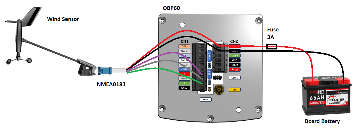
Fig.: NMEA0183 minimum configuration
Hint
Other sensors can be connected to the OBP40 in a similar way. However, it’s important to note that only one device or sensor can be connected to the OBP40 at a time. If multiple devices are to be integrated, a multiplexer is required.
Attention
Please note that NMEA0183 data transmissions require the same transmission speed and the same transmission protocol for both the sender and receiver. Otherwise, data transmission will not be possible. The NMEA0183 interface in the OBP40 does not support the RS232 protocol.
Most multiplexers have multiple NMEA0183 inputs and at least one NMEA0183 output. When using a multiplexer, all sensors are connected to the multiplexer’s NMEA0183 inputs, and the NMEA0183 output is connected to the OBP40. The multiplexer then combines the data streams from all sensors into a single data stream at the output, as described. Filters at the data output can be used to limit the data volume to only the most important data. In this example, the OBP40 is configured as a receiver. Bus system termination is disabled.
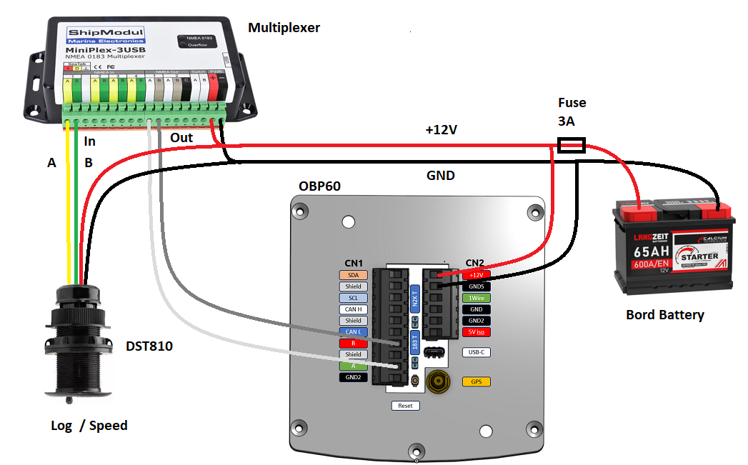
Fig.: NMEA0183 connection to a multiplexer
Hint
All NMEA0183 data is automatically converted to NMEA2000 by the OBP40 gateway. This conversion is unidirectional, only in the direction of NMEA2000. No data is converted in the reverse direction to NMEA0183, as the OBP40’s NMEA0183 port operates in receive mode in the configuration shown.
I2C
The I2C bus is used to connect electronic components. It is primarily used in electronics to connect various components on a circuit board in a cost-effective manner. The connection is made via a two-wire line and operates with signal levels of 5.0V. It includes the clock signal SCL and the data signal SDA. Communication operates as a master-slave system. The master controls the slaves via a unique address and can exchange data with them.
I2C specification in the OBP40
Serial, bidirectional, synchronous binary-based data protocol
Bus structure (isolated)
Half-duplex with collision detection and avoidance
Internal bus termination via pull-up resistors
- Supported protocols
I2C, TTL 5.0V
Data rate 100,000 kbit/s variable
Power supply for sensors and display devices via separate lines
Bus length up to 1 m
Cable type not specified
Connector type not specified
The OBP40 uses a 3.3V TTL signal level I2C bus. The connections are unprotected and come directly from the ESP32-S3. Keep in mind that the I2C bus cable length should not exceed 1 meter.
Exit |
Meaning |
|---|---|
5Visor |
Supply voltage |
GND2 |
Mass I2C |
Shield |
I2C shielding |
SCL |
Bus-Clock |
SDA |
Data line |
The following image shows an I2C bus setup with 3 I2C sensors. All sensors are connected to the I2C input on the OBP40 using shielded cables.
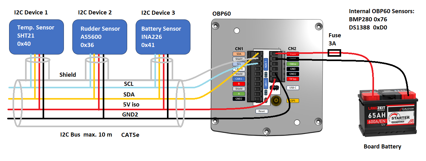
Fig.: I2C connection of external sensors
Note
For wiring external sensors, use shielded cables whenever possible and run the shield directly to the sensor. Connect the sensor cable shield directly to ground (GND).
Caution
If you intend to use external sensors or modules on the I2C bus, check whether an address conflict could occur between the sensors or modules. Ensure that I2C addresses are not assigned multiple times, as this will lead to communication problems on the I2C bus. In particular, when using multiple identical modules, the I2C addresses must be configured differently. This is not possible with some I2C modules. In such cases, you can only use one I2C module of the respective type on the bus. The OBP40 itself does not occupy any I2C addresses.
Caution
External I2C sensors that are not connected but are enabled in the configuration will impair the responsiveness of the OBP40. These sensors cannot respond to the system, resulting in a software timeout. In such a case, disable the sensors in the configuration.
Danger
Excessively long cables cause communication problems on the I2C bus. Faulty wiring can render the entire device inoperable. The I2C lines are unprotected and directly connected to the ESP32-S3. Overvoltages will destroy the ESP32-S3.
1Wire
The 1-Wire bus is a single-wire bus for serial data transmission in electronic circuits. In addition to the data line, a ground line is required for potential reference. Transmission is bidirectional and asynchronous. The 1-Wire bus is often used for simple sensors that transmit only small amounts of data, such as the DS18B20 temperature sensors. On the OBP40, the 1-Wire bus is accessible at terminal CN2.
1-Wire Specification
Serial, bidirectional asynchronous binary-based data protocol
Bus structure (not isolated)
Half-duplex with collision detection and avoidance
Bus termination via pull-up resistor at the output
- Supported protocols
1Wire, TTL 3.3V
Data rate 9600 kBit/s (with parasitic power supply via data line)
Power supply to sensors via data line
Bus length up to 10 m (depending on data rate and power supply)
Cable type not specified
Connector type specified for some applications
Maximum 8 DS18B20 sensors can be used.
The 1-Wire bus offers a simple and cost-effective way to integrate temperature sensors. Only 3 wires are required at the OBP40 for connection.
Exit |
Meaning |
|---|---|
1Wire |
Data line |
GND |
Masse 1Wire |
GND2 |
Shielding |
The temperature sensors are powered parasitically via the data line. Internally, each sensor contains a capacitor that stores a certain amount of energy for transmission when the data level is at 3.3V. The sensors are addressed via unique addresses and can exchange data with the OBP40. With this parasitic power supply, the data rate is limited to a maximum of 9600 kbit/s. The sensors can only be queried a few times per minute, as they need to accumulate energy over a longer period via the data line. Only one sensor is read per second. This process is then repeated for all subsequent sensors. Therefore, 1-Wire temperature sensors are only suitable for processing non-critical temperature values.
Below is an example application for 1-Wire temperature sensors.
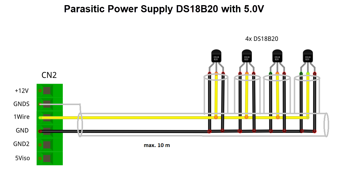
Fig.: 1-Wire connection of external temperature sensors (parasitically powered)
The DS18B20 temperature sensors are to be connected as follows.
Exit |
Temperature sensor |
|---|---|
1Wire |
Yellow, data line |
GND |
Black + red |
GNDS |
Screen |
Note
For wiring external temperature sensors, use shielded cables whenever possible and run the shield directly to the sensor. Do not connect the sensor cable shield to GND, as this will create ground loops. The entire shield of the bus cable must only be connected at one end to input GNDS of the 1-Wire bus on the OBP40. The shield at the other end of the cable remains open. Other shield inputs must not be used. Keep spur lines from the bus to the sensors as short as possible. The maximum number of sensors on the 1-Wire bus is limited to 8. The read time of a sensor depends on the number (N) of sensors on the bus. The read time T can be calculated using the following formula: T[s] = N * 1s.
Hint
If possible, use temperature sensors on the I2C bus instead of the 1-Wire bus. This increases the operational reliability of the overall system, as the I2C bus is isolated from the outside world.
Hint
Counterfeit DS18B20 temperature sensors are circulating online, but these do not support a parasitic power supply. If you cannot establish communication with the OBP40, try other sensors. If that also fails, use a standard power supply for the temperature sensors. Almost all sensors should work with this type of power supply.
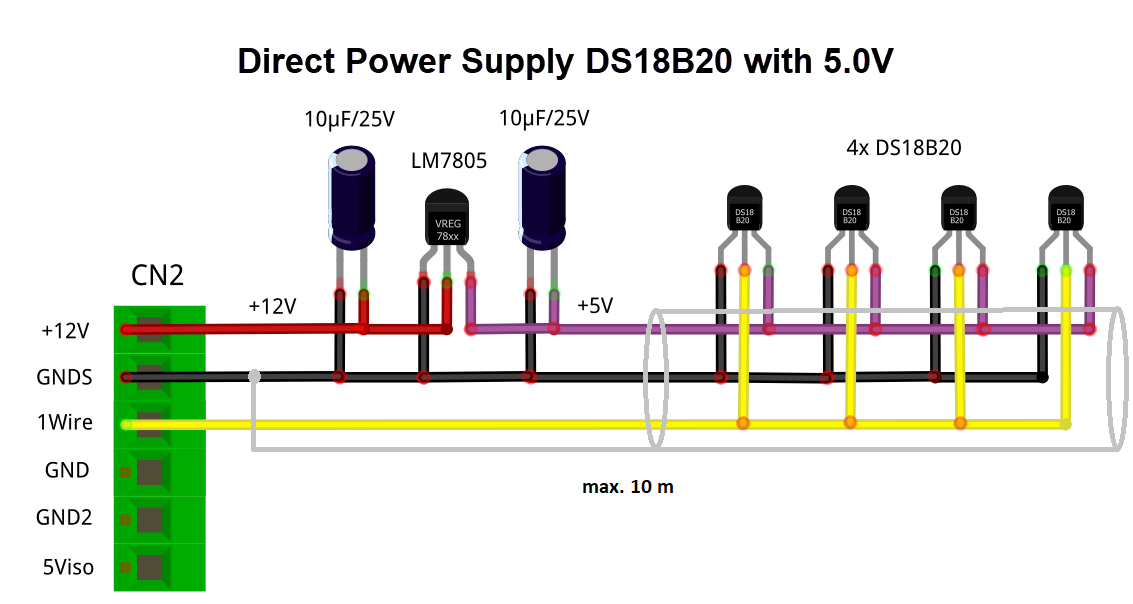
Fig.: 1-Wire connection of external temperature sensors (directly powered)
Caution
The 1-Wire bus is not isolated from the OBP40’s internal circuitry. If installed improperly, this increases the risk of interference coupled into the bus lines, which can impair the OBP40’s function and stability. Therefore, keep the bus length as short as possible. In the worst case, this can lead to the complete failure of the OBP40, with serious consequences for your boat’s navigation capabilities.
Danger
Under no circumstances should a voltage of 12V be applied to the output 1Wire. This will immediately damage or even destroy the OBP40.
USB
The USB-C interface on the OBP40 is used for flashing firmware and debugging. The USB interface is implemented as a serial interface. Furthermore, bidirectional, full-duplex NMEA0183 communication can be established with other devices such as a laptop, PC, or marine control server.
USB Specification in the OBP40
Serial, bidirectional asynchronous binary-based data protocol
Point to point (not isolated)
USB-OTG (serielles Device)
Full duplex
Bus termination via pull-up resistor in the ESP32
- Supported protocols
USB 1.1, TTL 3.3V
Data rate 1 MBit/s
The OBP40 can be powered via USB.
Powering external devices from the OBP40 is not possible
Bus length up to 3 m
Cable type: shielded
Connector type: USB-C
Note
For Linux and Windows 10/11, the necessary USB drivers are integrated into the operating system. For older Windows 7/8 versions, you need zusätzliche Treiber to use the USB interface.
Power supply
The OBP40 can also be powered via USB-C. This is useful, for example, when developing software and wanting to use the device at your desk. The power supply must be able to provide up to 1 A at 5.1 V, such as a Raspberry Pi power supply.
Communication
The USB-C interface can be used for full-duplex NMEA0183 communication with other devices. The following usage scenarios are conceivable:
Communication with a Marine Control Server
Data provider for an Android car radio as a plotter
Communication with a laptop or PC for software development, diagnostics and firmware flashing
Diagnosis of bus communication with external software such as the Actisense Reader
Feeding simulation data into the bus systems using the NMEA-Simulator