Data exchange
Internal data processing
The OBP40 firmware consists of two parts. The first part is the NMEA2000 gateway, and the second part is the hardware control of the OBP40. NMEA2000-Gateway is an open-source project by Andreas Vogel. It is software that enables bidirectional data conversion between NMEA2000 and NMEA0183. The software is designed to support various commercial hardware. For example, the NMEA2000 gateway runs on a range of products from M5Stack, such as the M5Stack Atom, as well as on ESP32 development boards like the ESP32 Node MCU. Different versions of the ESP32 CPU are supported, including the ESP32-Wroom and the ESP32-S3. The hardware control of the OBP40 is implemented via independent tasks and utilizes the basic functionality of the NMEA2000 gateway.
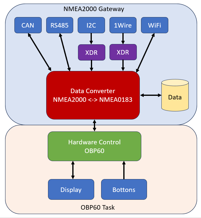
Fig.: Data flow diagram
All data processing for all bus systems and conversions is integrated into the NMEA2000 gateway. In addition to NMEA2000 (CAN) and NMEA0183 (RS485), other bus systems such as I2C and 1-Wire are supported. The main task of the NMEA2000 gateway is to receive all incoming data from the bus systems and store it in a common data pool. This data can be viewed via the Data webpage. Extended sensor technology, not part of NMEA2000 and NMEA0183, can be integrated via I2C and 1-Wire. This allows the use of cost-effective sensors. To enable the use of data from these extended sensors within the NMEA2000 and NMEA0183 networks, it is inserted into the data pool via NMEA0183 as universal XDR data records. The data can then be converted to NMEA2000 as XDR data sets, provided the converter has the necessary translations implemented. CAN, RS485, and WiFi are available as output interfaces. Only NMEA2000 data can be exchanged via the CAN interface. Both NMEA0183 and NMEA2000 data can be exchanged via RS485 and WiFi (TCP), provided the NMEA2000 data is tunneled through NMEA0183 in SeaSmart telegrams.
Data exchange in the OBP40 can occur in various ways. Basically, several transmission methods are available via different transmission paths:
Transmission methods
- Simplex
Data can only be transmitted in one direction.
- Half-duplex
Data can flow alternately, but not simultaneously, in both directions.
- Vollduplex
Data can be transferred in both directions simultaneously.
Transmission paths
- NMEA2000
Wired NMEA2000 bus (half-duplex)
Over WiFi via SeaSmart (full duplex)
- NMEA0183
Wired NMEA0183 bus (simplex)
USB (vollduplex)
Over WiFi via TCP (full duplex)
I2C (half-duplex)
1Wire (halbduplex)
Data sources
Data sources are devices that primarily send data to other devices and themselves only receive data for parameterization. These include the following devices:
GPS receiver (position, speed, direction)
Wind sensor (speed, direction, temperature)
Depth sensor (depth, speed, water temperature, distance traveled)
Angle sensors (rudder position, mast, boom, foil, trim tabs)
Electrical sensor (voltage, current, power, energy)
Environmental sensors (air temperature, air pressure, humidity, brightness, precipitation, condition, movement)
Flow sensors (cooling water flow, cooling water temperature)
Pressure and tension sensors (oil pressure, backstay, forestay)
Level sensors (for water, wastewater, fuel)
Position sensors (roll, pitch, yaw angle, acceleration, rotation, magnetic field)
Temperature sensors (air, cooling water, room, refrigerator, water, engine room)
Electric generators (solar, wind, towed diesel generator)
Radar devices (surroundings map)
Radio equipment (position, AIS ship traffic, callers, messages, distress calls)
Display devices (multifunction displays, plotters)
Video cameras (image, sound, motion)
Data sinks
Data sinks receive information and perform specific actions.
Rudder actuator (linear, rotary, hydraulic, electric)
Relays and switches (electrical consumers such as anchor winch, lights, navigation lights, ventilation, heating, chargers)
Angle actuator (trim flaps, foil adjustment)
Display devices (multifunction displays, plotters)
Multimedia devices (radio, speakers)
Some more complex devices can be both a data source and a data sink, such as multifunction displays or plotters.
The transmission methods are described in more detail below.
NMEA2000 - Cable bundled
The wired NMEA2000 bus is the current standard in boat networking. Various devices are connected to the bus system via a CAN-based NMEA2000 backbone. All bus participants can read and write data. Sensors act as data providers, transmitting their data to displays and chartplotters. The NMEA2000 backbone can also supply power to sensors. This power is supplied via a chartplotter or a power cable.

Fig.: NMEA2000 bus system with sensors and display devices
No special configuration is required for NMEA2000 operation. The default settings are configured to ensure trouble-free operation. If necessary, sending NMEA2000 telegrams can be disabled. In this case, only receiving NMEA2000 telegrams is possible. The NMEA2000 settings can be found under Config - Converter.
NMEA2000 - WiFi via SeaSmart
The SeaSmart protocol allows NMEA2000 telegrams to be transmitted over Ethernet and WiFi. This is achieved by embedding the binary data of the NMEA2000 telegrams into proprietary NMEA0183 telegrams. A SeaSmart telegram looks like this:
$PCDIN,a–a,b–b,b,cc,d–d*hh<CR><LF>
- Field number:
A - PGN im Binärform
B - Timestamp in binary form
C - Source-ID
D - PGN data in binary form
Hh - Checksumme
- Example:
$PCDIN,01F211,0B9CF01B,03,008061480D0000FF*5C
The advantage is that SeaSmart telegrams can be transmitted just like NMEA0183 telegrams. This makes it possible to wirelessly transmit NMEA2000 telegrams via Wi-Fi from one OBP40 to another. This function can be used, for example, to display bus sensor data from an OBP40 or an M0 on a daughter OBP40 device.
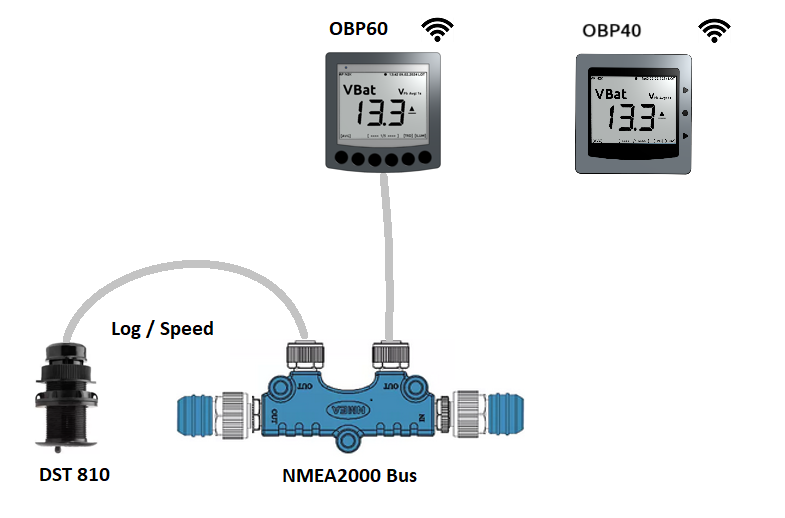
Fig.: Data transmission via WiFi OBP60 - OBP40
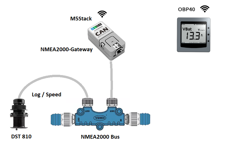
Fig.: Data transmission via WiFi M5Stack - OBP40
Hint
Both devices must be on the same Wi-Fi network and have different network names and IP addresses. One device must be configured as a TCP server and the other as a TCP client, and SeaSmart out must be enabled on both devices.
The following is a configuration example for the diagram above, showing data exchange via WiFi between an OBP60 and an OBP40. Device 1 is configured as a TCP server and device 2 as a TCP client. Device 2 connects to the WiFi network of device 1 and exchanges data bidirectionally.
Attitude |
Device 1 |
Device 2 |
|---|---|---|
System Name |
OBP60V2 |
OBP40V1 |
ApPassword |
11111111 |
22222222 |
ApIP |
192.168.15.1 |
192.168.16.1 |
SeaSmart Out |
On |
Off |
Enable |
Off |
On |
Remote Address |
— |
192.168.15.1 |
SeaSmart Out |
Off |
On |
WiFi Client |
Off |
On |
WiFi Client SSID |
— |
OBP60V2 |
WiFi Client Password |
— |
11111111 |
NMEA0183 - Cable bundled
Wired data transmission for NMEA0183 uses simplex transmission. This means you can either send or receive. By default, the OBP40 is set to receive. However, it is also possible to send NMEA0183 data. This setting is found under Config - Serial Port. The data direction can be set via Serial Direction.
This section demonstrates how data from an NMEA0183 multiplexer can be integrated into an OBP40. The multiplexer collects all sensor data via its inputs and generates a consolidated data stream at its output. The OBP40 then receives this data and can subsequently use it.
Note
The multiplexer configuration depends on the model. Consult the manual and ensure the correct baud rates are set for the multiplexer’s inputs and outputs.
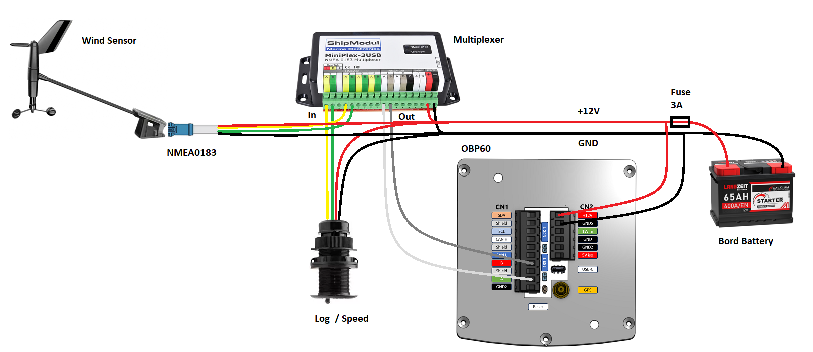
Fig.: NMEA0183 connection of an OBP60 to a multiplexer (receive)
Attitude |
OBP60 |
|---|---|
Serial Direction |
Receive |
Serial Baud Rate |
115200 |
Serial to NMEA2000 |
On |
Here’s an example of how to send NMEA0183 data to an autopilot. Data from the available communication channels is used and sent to the autopilot. The data output is filtered so that only relevant information reaches the autopilot. In this example, the autopilot uses an NMEA0183 input to RS422 or RS485 with an interface speed of 4800 baud. You may need to adjust the speed to suit your autopilot.
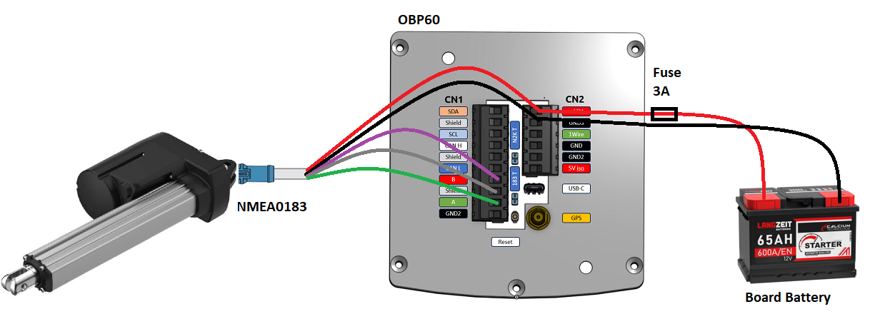
Fig.: NMEA0183 connection of an OBP60 to an autopilot (transmit)
Attitude |
OBP60 |
|---|---|
Serial Direction |
Send |
Serial Baud Rate |
4800 |
Serial to NMEA2000 |
On |
Serial Read Filter |
— |
Serial Write Filter |
XTE,XDR,RMB,RMC,ROT |
Only the NMEA0183 telegrams XTE, XDR, RMB, RMC and ROT are sent to the autopilot.
Note
Check the autopilot documentation to see if the transmitted NMEA0183 telegrams can be used for navigation and are sufficient. In some cases, the autopilot may use different telegrams for course control. If so, the autopilot cannot be controlled.
NMEA0183 - USB
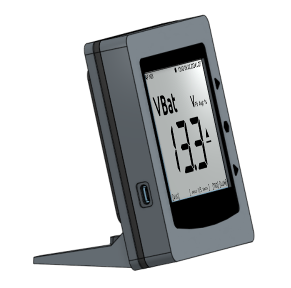
NMEA0183 telegrams can also be transmitted full-duplex via USB. This means that data can be sent and received simultaneously. The USB port for data transmission is located on the left side of the OBP40. It is a USB-C port. The USB interface in the OBP40 is implemented as a serial RS232 device and supports transmission speeds of 1,200 to 460,800 baud. The default setting for data transmission is 115,200 baud, which should be sufficiently fast for most applications. Data is transmitted exclusively as NMEA0183 data via USB.
The following hardware could be used as possible endpoints:
Raspberry Pi 3, 3B, 4B, 5
Android Autoradio
Laptop
PC
The NMEA0183 data can be integrated into various software programs such as:
AvNav
OpenPlotter
OpenCPN
BBN
SignalK
QtVlm
Navionics
WinGPS
NMEA Simulator
The following settings must be configured in the OBP40 for all endpoints listed above. This allows NMEA0183 data to be received and sent via the USB interface and simultaneously converted bidirectionally to NMEA2000.
Attitude |
OBP40 |
|---|---|
Log Level |
Off |
USB Mode |
Nmea0183 |
USB Baud Rate |
115200 |
NMEA to USB |
On |
NMEA from USB |
On |
USB to NMEA2000 |
On |
Hint
Ensure that the Log Level is set to off. Otherwise, communication problems may occur because logging output will be included in the data stream, which is also transmitted via USB-C.
NMEA0183 - WLAN
The TCP client can receive NMEA0183 telegrams (similar to USB transmission), for example, from a Raspberry Pi running OpenPlotter or SignalK. The TCP client must be configured accordingly.
Configuration examples
The following are some configuration examples. They show how to further configure the system.
Example AVnav on Raspberry Pi
This example demonstrates the integration of an OBP40 via USB into AvNav, which is running on a Raspberry Pi. NMEA2000 bus data is read and transferred to NMEA0183. The connection is established directly within AvNav as a device, and the data is then available to the application. In this case, the AvNav image is used. Users of AvNav as a plugin under OpenPlotter should follow the OpenPlotter on Raspberry Pi Configuration Example.
To connect the OBP40 and the Raspberry Pi, you will need a USB-C to USB-A cable. You can use any USB-A port on the Raspberry Pi.
Hint
It is advisable to use the black USB-A ports on the Raspberry Pi, as the OBP40 only supports USB 1.1, thus leaving the more powerful USB 3.0 ports free for other uses. Be sure to supply the OBP40 with an additional 12V power supply, as the Raspberry Pi does not provide enough power through its USB ports.
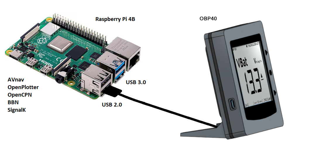
Fig.: Connection OBP40 - Raspberry Pi
Warning
Use only high-quality, shielded USB-C cables to connect the OBP40 to the Raspberry Pi. The cable length should not exceed 1.5 m to prevent excessive signal loss and ensure a high data transfer rate. For longer distances, use active USB extension cables.
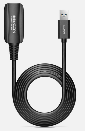
Fig.: Active USB extension cable for 5 m
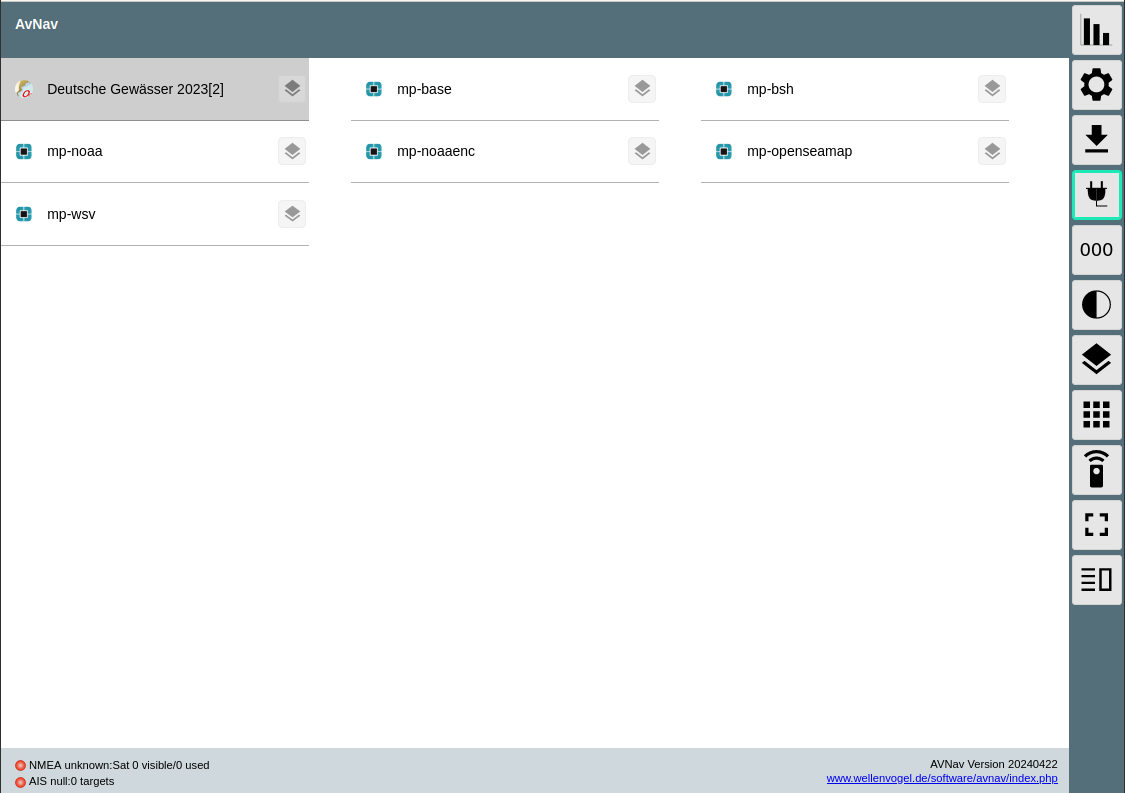
Image: AvNav Homepage
Under AvNav, click the icon with the 3 lines in the top right corner of the homepage.

You will then be taken to the server status page.
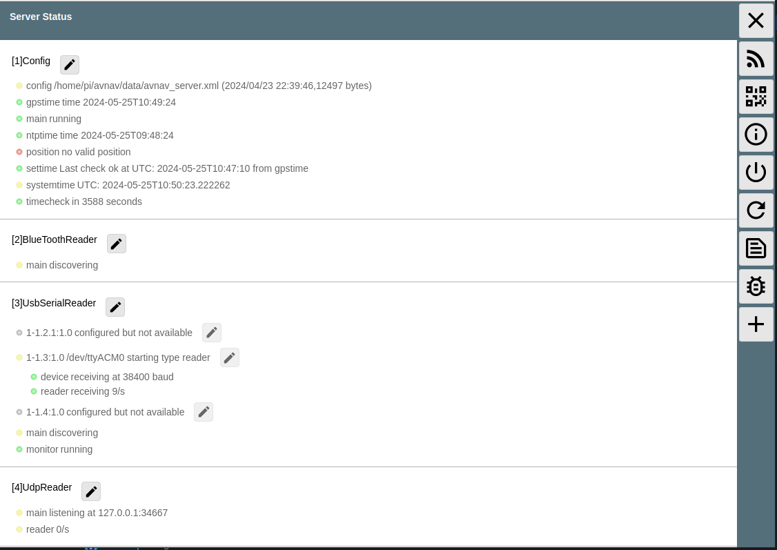
Fig.: Server status without OBP40
AvNav is configured to automatically detect and assign all serial USB devices. Both the device and its data rate are recognized. First, get an overview of which devices are already connected via USB. In the image above, under item [3] USBSerialReader, you can see all currently detected and assigned devices. In our case, a GPS dongle is already connected via USB. The device is assigned to the interface /dev/ttyACM0 and operates at a data rate of 38,400 baud.
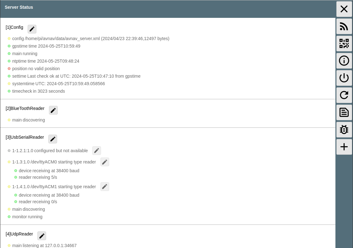
Fig.: Server status with OBP40 (not yet configured)
When you connect the OBP40 to the Raspberry Pi via USB, you’ll see a newly added device /dev/ttyACM1 in the image above, under point 3. This is the OBP40. However, the interface speed is not yet configured correctly.
Clicking the pencil icon next to the line containing /dev/ttyACM1 allows you to configure the device settings. The following values need to be adjusted:
Baud
115200Type
combinedName
OBP40V2
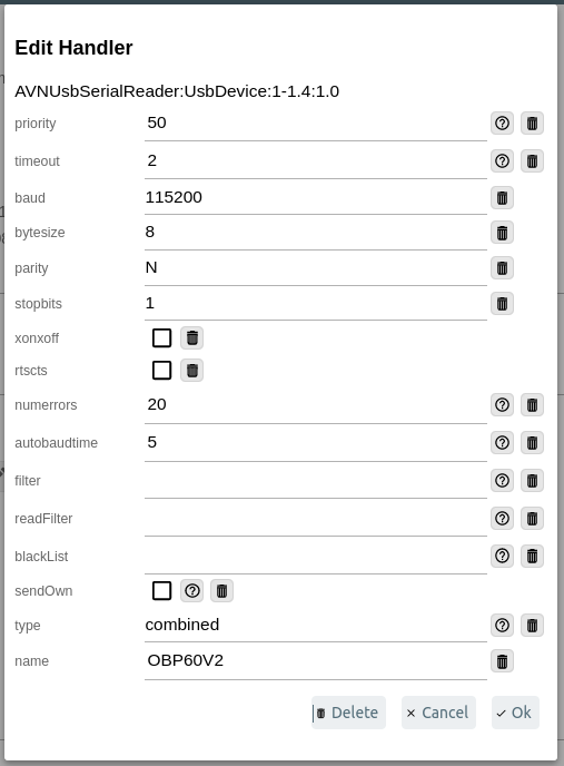
Fig.: Settings for the OBP40
Changing the type from read to combined enables bidirectional communication via USB with a transfer speed of 115200 baud. The OBP40 is now connected to AvNav. As long as you use the same USB ports, the USB devices will be correctly assigned and the transfer speed set correctly after each system restart.
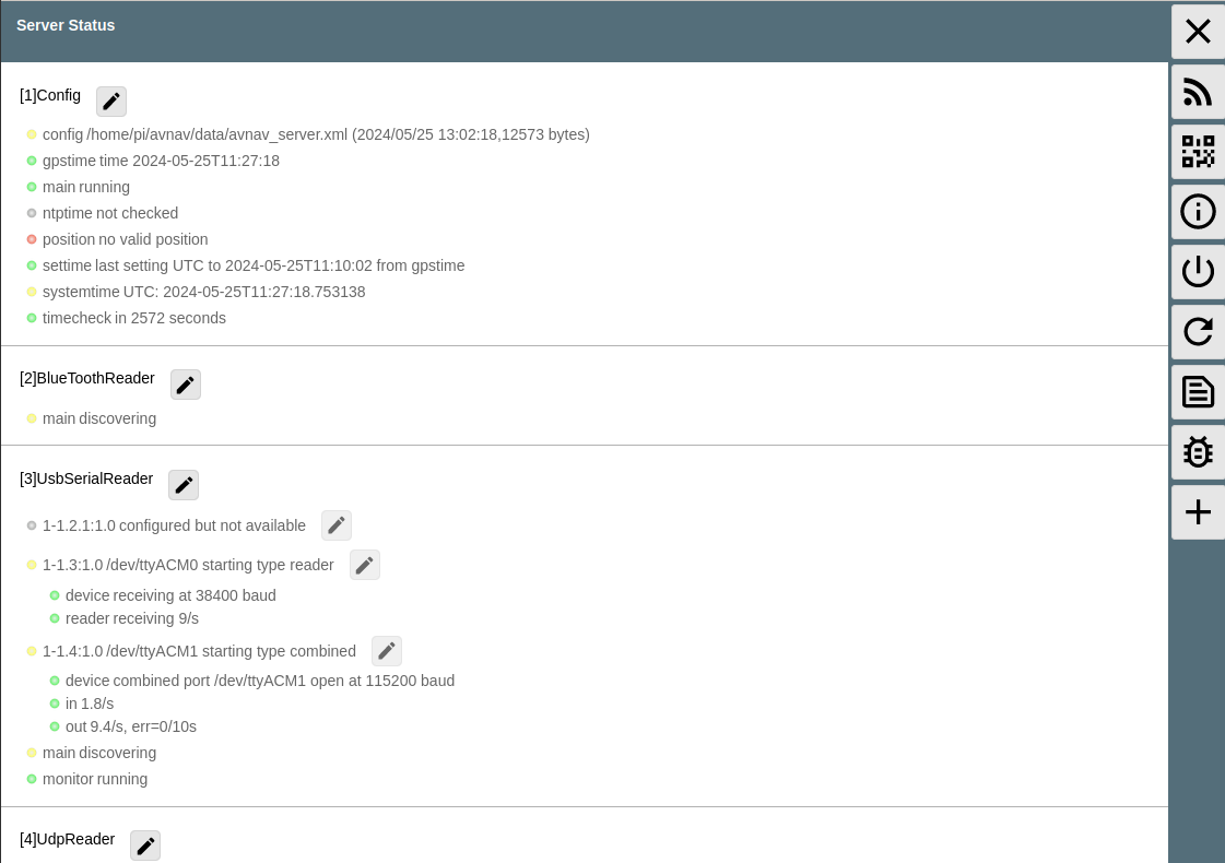
Fig.: Server status with OBP40 (correctly configured)
Example AvNav on Android car radio
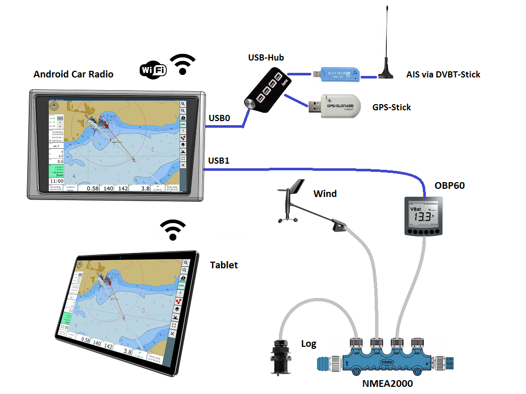
Fig.: Connection OBP60 - Android car radio AvNav
This example demonstrates how to input bus data into an Android radio so that the data can be used in AvNav. For data transfer to the Android car radio, you will need a USB-C to USB-A cable, provided a suitable adapter port is available. In some situations, you will need to connect the USB cable directly to the car radio using special connectors. Consult your Android car radio’s manual and establish the USB connection as instructed.
Warning
Use only high-quality shielded USB-C cables to connect the OBP40 to the Android car radio. The cable length should not exceed 1.5 m to prevent excessive signal loss and ensure a high data transfer rate. For longer distances, use active USB extension cables.
Fig.: Active USB extension cable for 5 m
Hint
Configuring AvNav for Android differs in a few steps from the server version of AvNav on a Raspberry Pi. Note that Android does not offer automatic configuration of serial USB devices. USB devices must always be added manually.
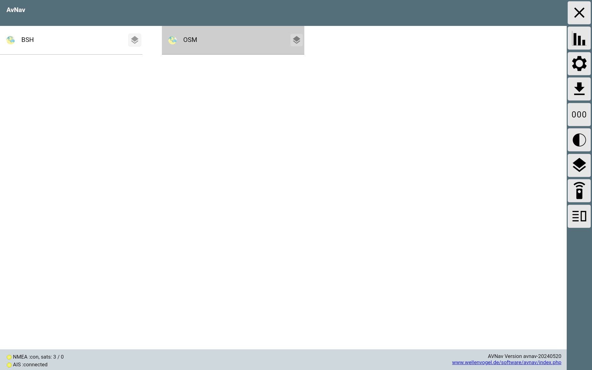
Image: AvNav homepage for Android
Under AvNav, click the icon with the 3 lines in the top right corner of the homepage.
You will then be taken to the server status page. There, you can establish additional connections to the AvNavServer using the plus symbol.

For bidirectional communication via USB, select UsbConnection.
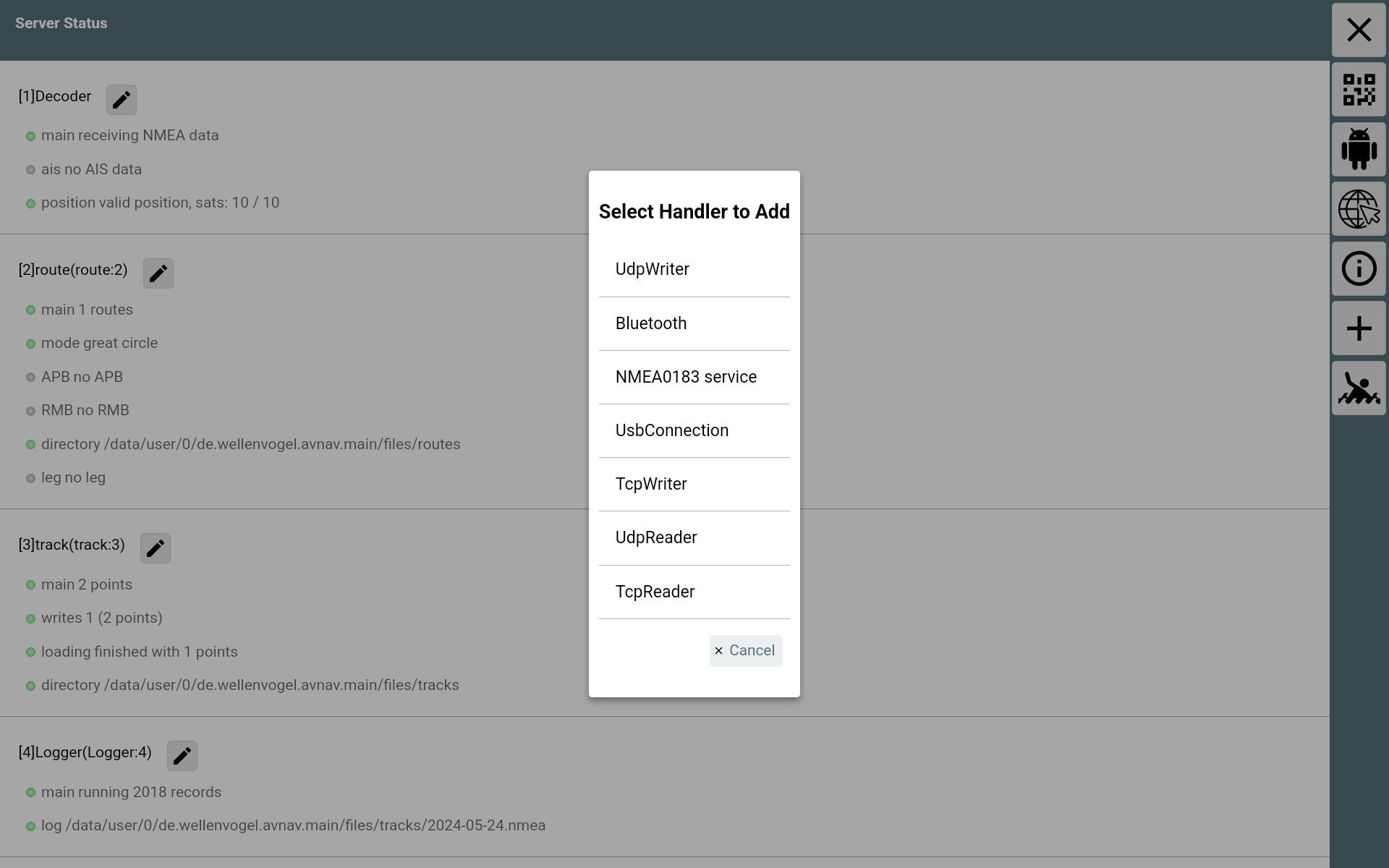
Fig.: Connection types
Under Device, select the serial connection to which the OBP40 is connected to the Raspberry Pi (/dev/bus/usb/001/003). Set the interface speed to 115200 Bd. To be able to not only send but also receive data, enable SendOut.
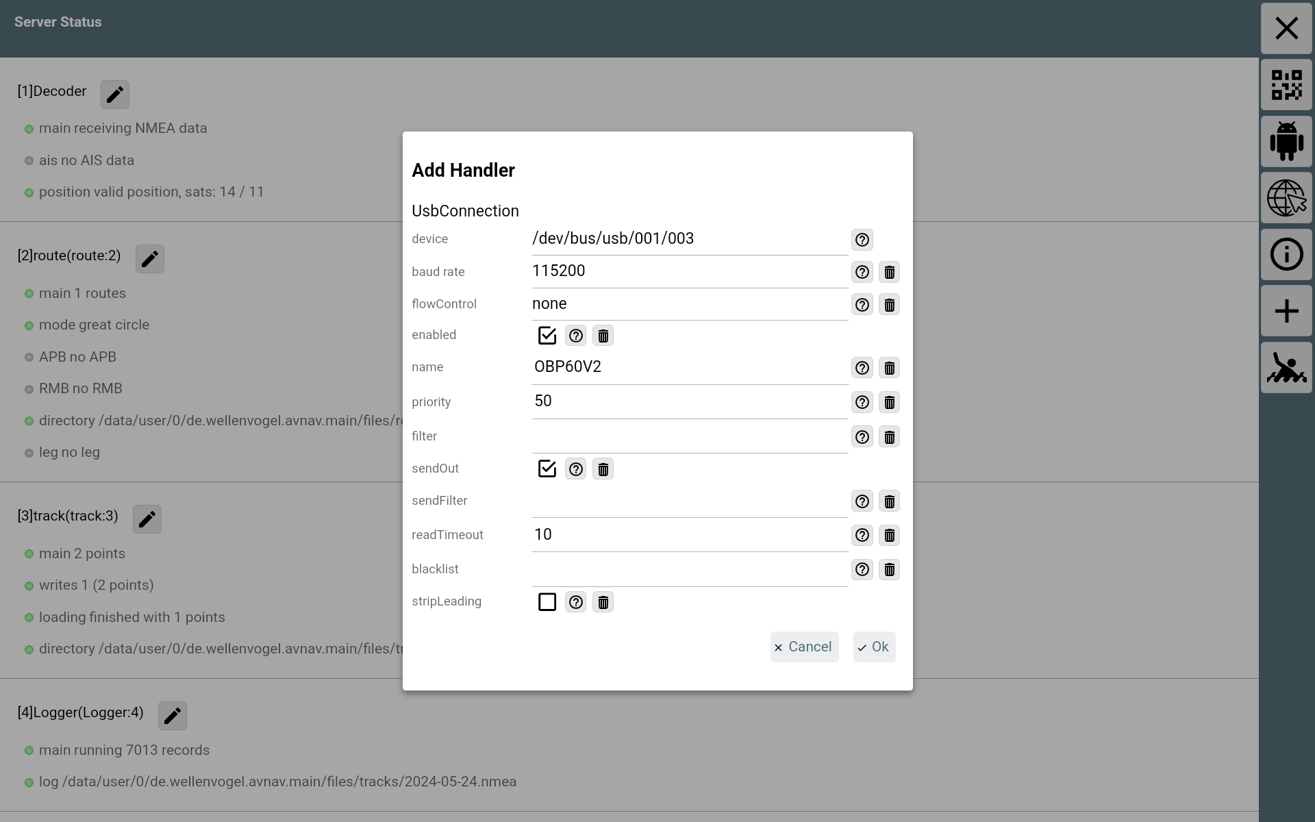
Fig.: USB connection settings
Once all data has been transferred, the new connection can be seen in the server status.
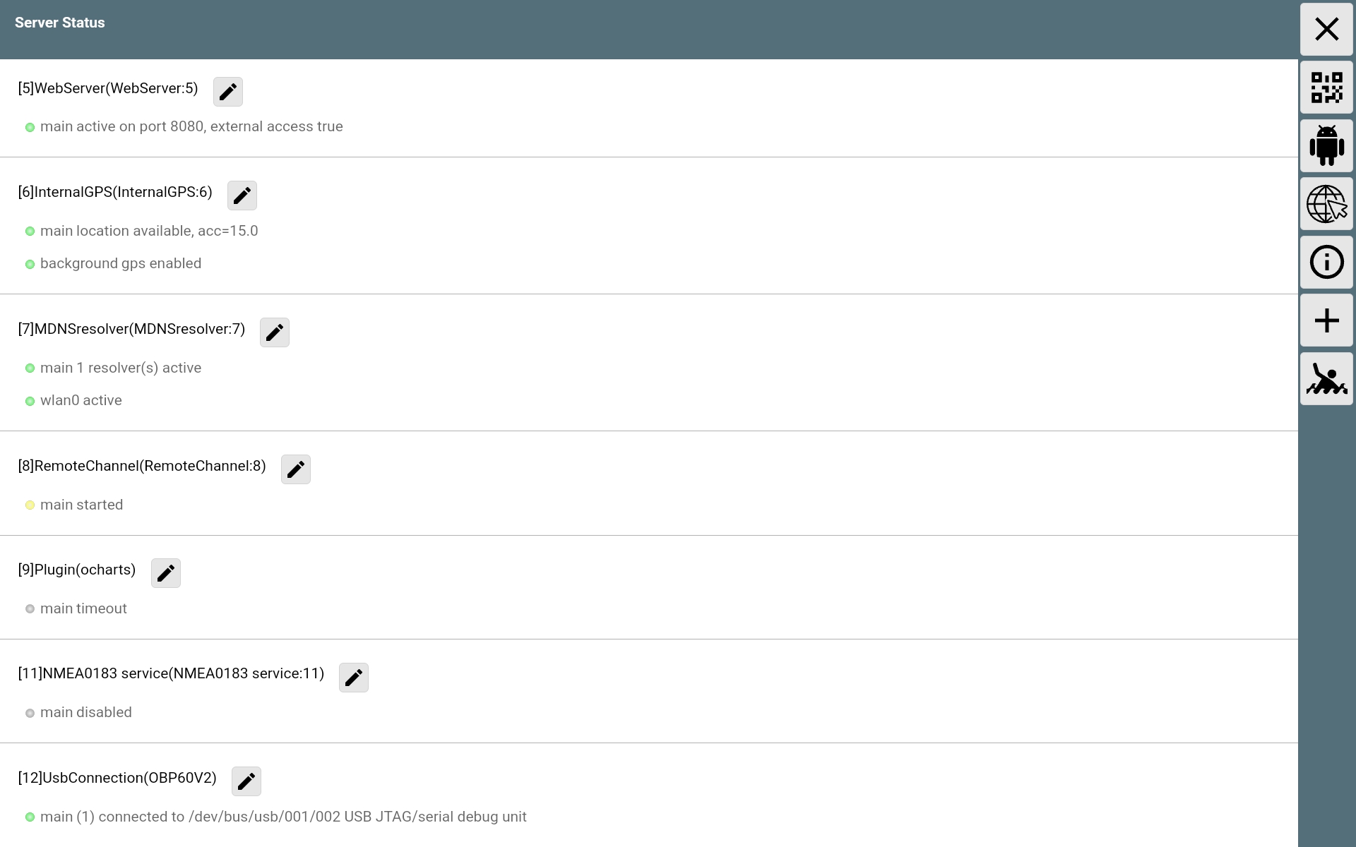
Abb.: Server-Status
Example SignalK on Raspberry Pi
SignalK can distribute the available data in NMEA0183 format over the Wi-Fi network. One advantage of this method is that no data cable is required to the OBP40; only the Raspberry Pi and the OBP40 need to be connected to the same Wi-Fi network. For this to work, the server option Settings NMEA 0183 over TCP (10110) must be enabled in SignalK.
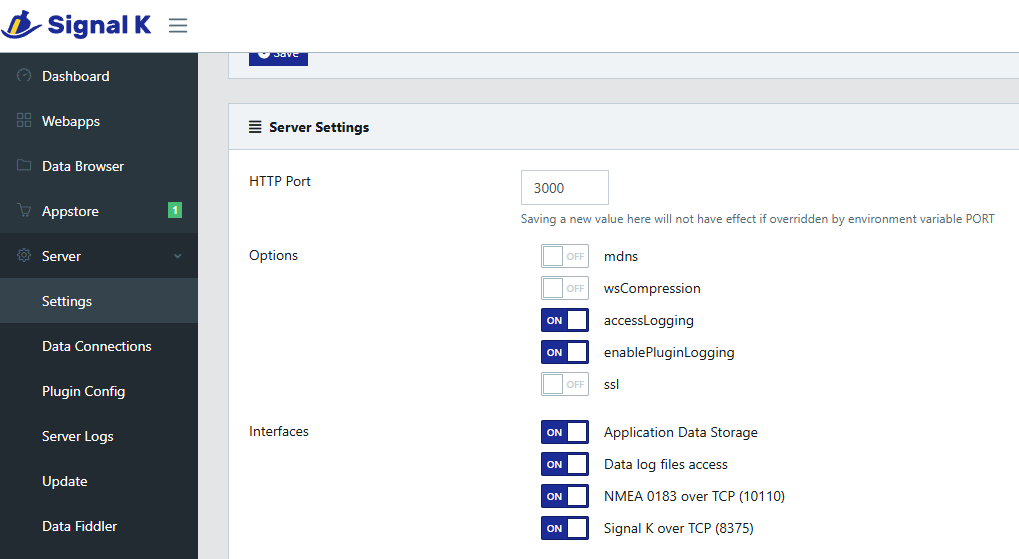
Abb.: SignalK Server
In addition, the signalk-to-nmea0183 plugin must be installed and activated, in whose configuration you can select which NMEA0183 data should be output.
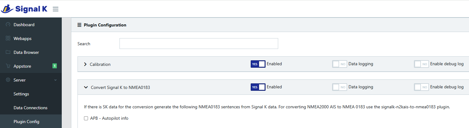
Abb.: SignalK Plungin
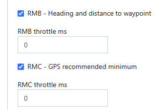
Fig.: SignalK Plungin configuration example
To test this functionality, you can display the data stream on the Raspberry Pi using the following command in a terminal: nc localhost 10110
The data provided in this way can be retrieved using the Config - WiFi Client of the OBP40 and is then available on the Data page and can be selected for display on the individual pages.
Example OpenPlotter on Raspberry Pi
OpenPlotter provides all available data via SignalK. From there, the data can be retrieved in NMEA0183 format using a TCP client, or transferred using the signalk-to-nmea2000 plugin.
Example: Navionics on an Android car radio
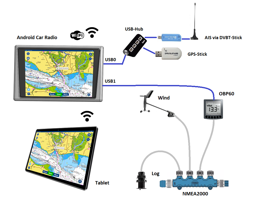
Abb.: Connection OBP60 - Android car radio Navionics
This example demonstrates how to input bus data into an Android car radio so that the data can be used in Navionics. For data transfer to the Android car radio, you will need a USB-C to USB-A cable, provided a suitable adapter port is available. In some situations, you will need to connect the USB cable directly to the car radio using special connectors. Consult your Android car radio’s manual and establish the USB connection as instructed.
Note
Due to the navigation software, not all bus data can be used in Navionics. Currently, only some data can be utilized. The following list shows the currently processable NMEA0183 Sentences.
AIVDM (AIS data)
AIVDO (AIS data)
DBT (Depth below sensor)
DPT (Corrected Depth)
GGA (Position)
GLL (Position)
RMC (Required minimum navigation data - time, position, course, speed)
VTG (Course and Speed over Ground)
ZDA (Time and Date)
I2C bus
Example I2C rudder position sensor
This section demonstrates how to use an I2C angle sensor as a rudder position sensor on the I2C bus. Basically, the angle sensor can be used for the following angle measurements:
Rudder position
Wind direction
Mast alignment for rotating masts
Keel inclination
Angle sensor for trim tabs or foils
Großbaum
A small circuit board with an AS5600, accessible at address 0x36, is used as an I2C angle sensor. The AS5600 is a magnetic angle sensor that detects the orientation of a magnetic field. The rudder deflection can be measured via a diametrically opposed magnet, whose magnetic field is split in the plane of the rudder and connected to the rudder axis. The magnet corresponds to the rudder’s axis of rotation.
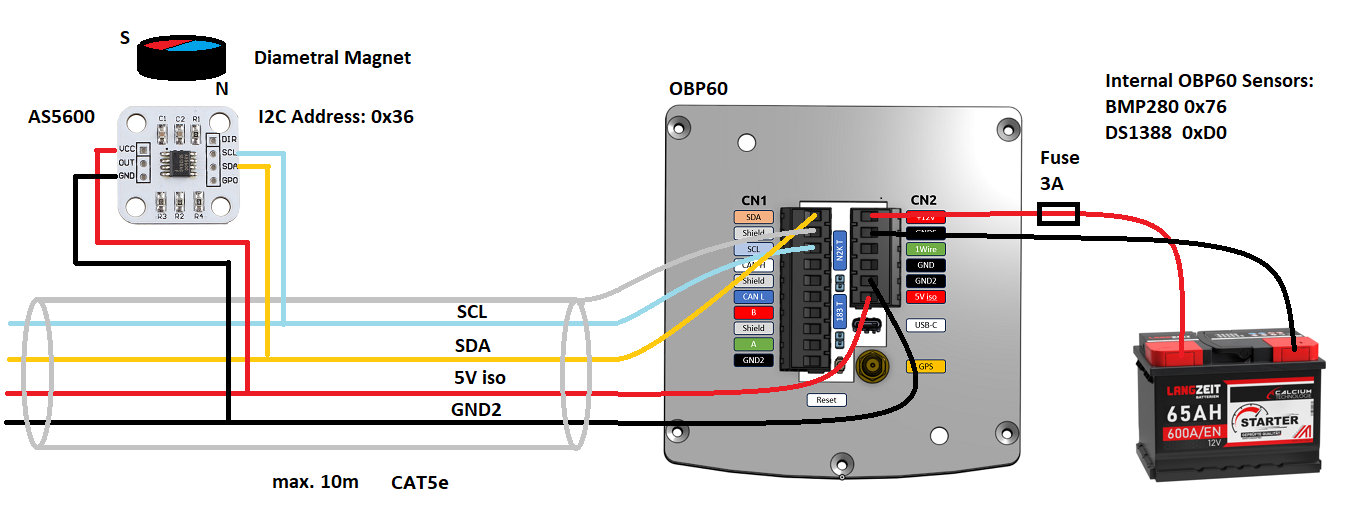
Fig.: I2C connection of the AS5600 magnetic protractor
Note
Note that only an AS5600 can be used as an angle finder, as its I2C address is not changeable. The connecting cable should be shielded and not exceed 10 meters in length.
The following settings must be configured on the OBP60.
Attitude |
OBP60 |
|---|---|
Rot. Sensor |
AS5600 |
Rot. Function |
Rudder |
Rot. Offset |
0 |
Depending on requirements, the offset must also be set via Rot. Offset.
1Wire-Bus
Up to eight DS18B20 temperature sensors can be connected via the 1-Wire bus. This allows temperatures ranging from -55°C to 125°C to be measured at various locations on the boat. The sensors are available as electronic components in a transistor package (TO-92) or in a waterproof metal housing with a cable. The latter version is best suited for marine applications.
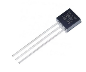
Abb.: DS18B20 TO-92
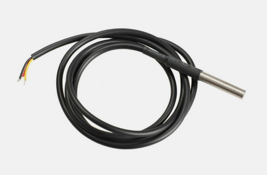
Fig.: DS18B20 Waterproof
If you want to measure temperatures at different points on the boat, create a backbone with junction boxes and connect the sensors to the junction boxes. This prevents unintentionally long branch lines in the 1-Wire bus system.
1-Wire configuration example
The lower image shows a circuit using four DS18B20 sensors. The sensors are powered directly via an LM7805 voltage converter. This circuit works with all sensors currently available on the market.
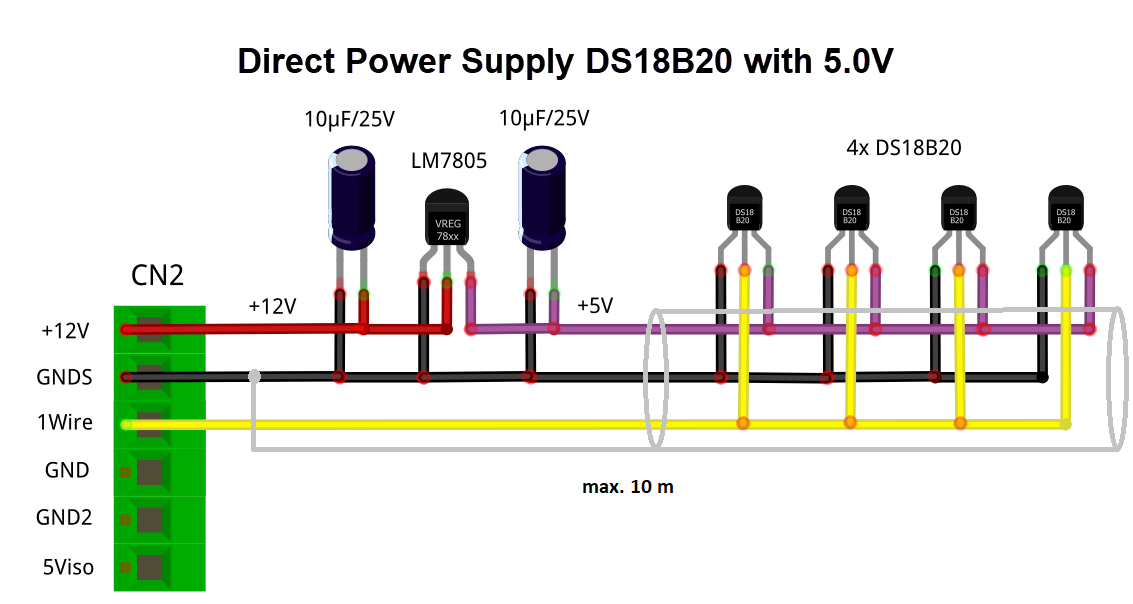
Fig.: 1-Wire connection of external temperature sensors (directly powered)
Attitude |
OBP60 |
|---|---|
Temp. Sensor |
DS18B20 |